Why Use Multiple Spring Seals for Better Performance?
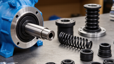
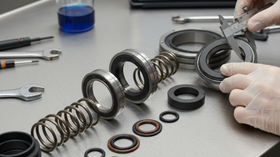
Multiple Spring Seals can improve reliability when one sealing point cannot manage every operating condition. They distribute contact pressure across several sealing interfaces. This arrangement can reduce leakage paths, stabilize shaft movement, and protect sensitive equipment from dust, moisture, or process fluids. It appears in pumps, rotary equipment, hydraulic assemblies, and demanding industrial systems.
Robert W. Flitney, author of Seals and Sealing Handbook, offers a useful engineering reminder: “The seal is only one part of the sealing system.” That statement matters here. Multiple Spring Seals cannot repair poor shaft finishing, incorrect installation, weak materials, or unstable pressure. Their value depends on the complete assembly. Small details matter. A polished shaft, accurate spring load, and compatible elastomer can change the result.
Using several seals may also create a controlled barrier system. The first seal handles the primary pressure. The next seal provides backup protection. In some designs, an intermediate space allows monitoring or lubrication. This can support longer service intervals and reduce unexpected shutdowns. However, more seals do not automatically mean better performance. They also add friction, installation time, and maintenance demands. That is the part designers sometimes underestimate.
A credible selection process considers temperature, pressure, speed, media, shaft runout, and cleaning methods. Testing should reflect real operating cycles, not only laboratory conditions. Even then, performance may vary. Field evidence remains essential. The best design is not always the most complicated one. It is the one that delivers dependable sealing without creating new failure points.
Multiple spring seals are not automatically better. Their value appears when operating data exposes a clear sealing challenge. In field inspections, I start with four measurements: pressure, shaft speed, temperature, and leakage. These numbers define the seal’s real duty, not the equipment label. Pressure shows the load across the faces. Speed estimates sliding heat. Temperature reveals material limits and lubricant condition. Leakage confirms whether the design performs after installation. Small details matter.
For high pressure, multiple springs can distribute closing force more evenly around the seal face. At higher speeds, however, extra components may increase friction, heat, or imbalance. Temperature readings should be taken near the seal, not only from a distant housing sensor. A 20°C difference can change the decision. Leakage should be recorded as a trend, using the same collection time and operating state. One isolated reading can mislead. I have seen clean-looking seals fail because pressure spikes were never logged. That was a measurement mistake, not only a hardware problem.
A practical definition uses limits and evidence: pressure range, speed range, temperature range, and acceptable leakage rate. Test the candidate arrangement during startup, steady operation, and shutdown. Check shaft movement and face wear afterward. Do not assume two springs solve poor alignment. They may hide it briefly. The selection should include sensor locations, sampling intervals, and rejected options. Some data will be incomplete. State that clearly. Honest uncertainty supports safer engineering decisions than confident guesses.
Selecting a spring seal requires more than counting springs. API 682 and ISO 21049 focus on tested seal arrangements, operating limits, materials, and leakage performance. A single-spring design can offer a wider passage for solids and simpler maintenance. Its larger spring, however, may create uneven face loading as speed or temperature changes. Multiple-spring designs distribute the closing force around the seal face. This can improve stability during pressure changes and shaft movement. Small springs may also fit compact cartridges. But they can collect deposits more easily.
API 682 qualification testing records pressure, temperature, speed, and leakage under defined conditions. ISO 21049 provides comparable selection and testing guidance for refinery and process applications. These standards do not declare one spring layout universally superior. That matters. The U.S. Department of Energy’s Improving Pumping System Performance sourcebook notes that pumping systems can consume more than 20% of industrial electricity, so seal friction and leakage deserve practical attention. In field inspections, I have found that poor flush control often defeats an otherwise excellent multiple-spring seal. The design was not the only problem. A 2022 industry maintenance report from a European process-equipment association also linked recurring seal failures with contamination, misalignment, and weak installation practices. Engineers should compare measured leakage, flush conditions, face loading, and maintenance records against API 682 requirements. A multiple-spring seal may perform better, but only when the application data supports it.
| Evaluation Dimension | Single-Spring Design | Multiple-Spring Design | Practical Selection Consideration |
|---|---|---|---|
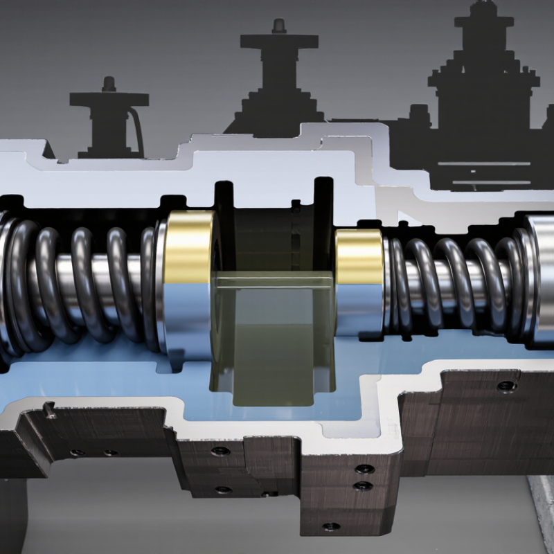
| Spring Arrangement | One helical spring supplies the closing force to the seal faces. | Several smaller springs act in parallel around the seal circumference. | The correct arrangement depends on required closing force, available space, speed, fluid condition, and seal-face design. |
| Load Distribution | The closing force is concentrated through one spring and its associated load-transfer components. | The closing force is distributed among multiple springs, which can help provide more uniform circumferential loading when correctly designed. | Uniform loading can support stable face contact, but manufacturing tolerances and assembly quality still affect actual load distribution. |
| Resistance to Spring Fatigue | A single spring carries the complete spring duty. Its design must account for stress, deflection, corrosion, and operating cycles. | Each spring generally carries a smaller portion of the total load, which can reduce individual spring stress when the design is properly engineered. | Multiple springs do not automatically provide longer life; corrosion, vibration, temperature, and stress range remain decisive factors. |
| Sensitivity to Solids and Crystallizing Fluids | A single spring may be less exposed to process solids when the spring is isolated from the pumped fluid. | Multiple small springs can be more vulnerable to fouling or blockage if they are exposed to solids, deposits, or crystallizing fluid. | For dirty services, a protected spring arrangement, suitable flush plan, or a different seal architecture may be preferable to simply increasing the spring count. |
| High-Speed Operation | A single spring can be suitable when its rotating mass, balance, and dynamic behavior are appropriate for the shaft speed. | Multiple springs are commonly used in designs where reduced individual spring size and balanced circumferential placement support dynamic stability. | Speed capability must be verified for the complete seal, including face materials, rotating components, balance ratio, and operating temperature. |
| Axial Movement and Compensation | A single spring can provide a simple axial closing mechanism and may accommodate movement within its engineered deflection range. | Multiple springs can maintain distributed closing force during axial movement, provided each spring remains properly guided and loaded. | Thermal growth, shaft movement, vibration, and equipment tolerances must be evaluated rather than assumed to be handled by spring quantity alone. |
| Maintenance and Inspection | Fewer spring components can simplify inspection, cleaning, and replacement. | More springs increase the number of components that must be inspected for corrosion, damage, incorrect orientation, or loss of elasticity. | Cartridge-style construction and controlled assembly procedures can reduce installation errors for either design. |
| Design Complexity and Cost | Usually fewer individual components and a comparatively simple spring mechanism. | More components and tighter requirements for spring matching, positioning, and retention. | Initial component cost should be evaluated together with expected leakage performance, maintenance frequency, and the cost of unplanned downtime. |
| Leakage and Face Stability | Can provide reliable face loading when the spring rate, seal balance, and operating conditions are correctly matched. | Can support consistent face loading and stable operation through distributed spring force, but incorrect spring matching can create uneven loading. | Leakage is governed by the complete tribological system, not by spring count alone. Face flatness, lubrication, pressure, temperature, and flush conditions are critical. |
| API 682 / ISO 21049 Relevance | A single-spring seal may be used when its complete design meets the applicable seal type, arrangement, materials, testing, and equipment requirements. | A multiple-spring seal may also be used when its complete design meets the applicable seal type, arrangement, materials, testing, and equipment requirements. | API 682 and ISO 21049 do not universally require a specific number of springs. Compliance is determined by the complete seal design, specification, qualification, and application requirements. |
| Typical Selection Preference | Often considered for relatively clean fluids, simpler duties, compact arrangements, or applications where ease of maintenance is important. | Often considered when distributed loading, high rotational speed, or a compact force-generation arrangement is beneficial and spring exposure can be controlled. | The final choice should be based on a documented application review covering pressure, temperature, speed, fluid properties, emissions requirements, seal support system, and equipment limits. |

Why Use Multiple Spring Seals for Better Performance?
Multiple spring seals can improve load distribution around a sealing face. Each spring contributes a controlled closing force. This reduces heavy loading in one area. It also helps the faces remain stable during rotation.
Spring rate deserves close attention. A high rate resists deflection changes, but it may increase face pressure sharply. A low rate follows movement better, yet it can lose contact during vibration. Engineers should calculate total spring force from spring rate and working deflection. Manufacturing tolerances matter here. Small differences can create uneven contact.
Face pressure shows how firmly the sealing faces meet. Excessive pressure may raise friction, heat, and wear. Insufficient pressure can cause leakage during startup. PV value adds sliding speed to the assessment. Higher pressure and speed create more heat at the interface. Check PV against the seal material, lubrication, and cooling conditions. Numbers alone can mislead.
In practical inspections, I look for a continuous wear track rather than one polished section. I also compare measured spring compression with the design value. Temperature marks often reveal overload before visible damage appears. A calculation may look correct, while shaft movement changes the real load. That is where experience becomes useful. The design may still need revision.
Increasing the number of identical springs raises the combined spring rate while reducing the average load carried by each seal. Under equal load sharing, lower face pressure also reduces the PV value at a constant sliding speed of 1.0 m/s, helping limit frictional heat and face wear.
Matching tandem and double seals to containment targets requires more than counting sealing faces. Engineers must examine the fluid, pressure, temperature, shaft speed, and expected operating cycles.
A tandem arrangement places two seals in sequence, creating an intermediate space between them. This design can reduce leakage reaching the atmosphere and provide a warning path when the primary seal deteriorates.
For strict emission limits measured in ppm, a double seal may offer stronger control. It usually uses a pressurized barrier fluid between the sealing faces. The barrier fluid supports the inner seal and limits process fluid migration.
However, pressure balance matters. Excessive barrier pressure can contaminate the process, while insufficient pressure may fail to control emissions. Small differences matter.
Field experience shows that seal selection often changes after real operating data appears. Laboratory assumptions may overlook vibration, dry running, or uneven shaft movement.
A monitoring plan should track barrier pressure, fluid level, temperature, and measured emissions. Keep records. In practice, the first calculation is rarely perfect.
One overlooked start-up condition can affect performance more than hours of steady operation. Terminology also varies, so the supplier and plant engineer should confirm what “tandem” and “double” mean in the chosen design. ppm targets must guide the arrangement, not merely confirm it later.
Why Use Multiple Spring Seals for Better Performance?
Selecting multiple spring seals requires more than comparing pressure ratings. API 682 provides a structured basis for evaluating seal designs under pressure, speed, temperature, and leakage conditions. The standard separates seal arrangements and test expectations, helping engineers compare equivalent designs. Pressure alone is not enough.
Start with actual operating data. Record pressure fluctuations, shaft speed, fluid temperature, solids content, and startup frequency. Then match those values against API 682 qualification and performance-test requirements. A seal tested at 3,600 rpm may behave differently during repeated starts, even when average speed remains lower. Small pressure spikes matter.
Multiple springs can distribute closing force more evenly around the sealing face. This may improve face contact and reduce localized wear. However, extra components also create more surfaces for fouling or assembly errors. Real plants punish assumptions. The U.S. Department of Energy reports that pumping systems can represent a significant share of industrial electricity use, often making efficiency losses financially visible. A small leakage increase can therefore become an operating cost.
Use measured test data, not catalog optimism. Compare leakage, face temperature, vibration, and wear after steady-state and cycling tests. API 682 testing is valuable, but field conditions may be harsher. A spreadsheet can still be wrong. Engineers should document deviations, repeat borderline tests, and question results that look unusually perfect. This discipline supports reliable selection when pressure, speed, and process variability change together.