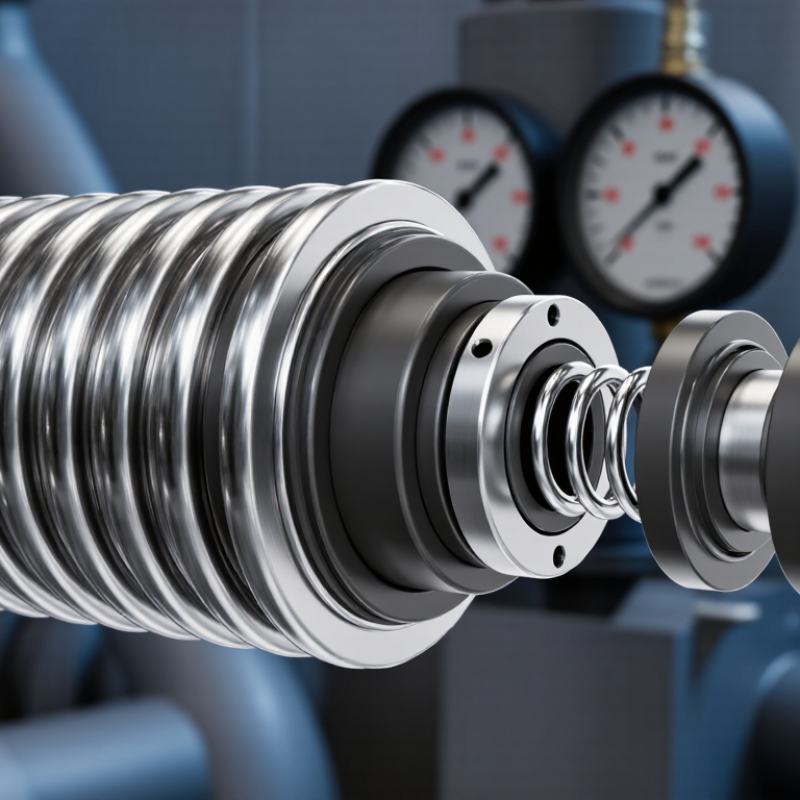
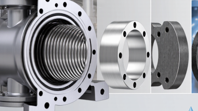
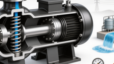
Choosing a mechanical seal is not just a matter of matching pipe size. Metal Bellow Mechanical Seals are often considered when equipment faces heat, pressure changes, vibration, or limited installation space. Their welded metal bellows provide spring force and accommodate some shaft movement without a separate dynamic elastomer secondary seal. Small design details matter.
Begin with the operating conditions, not a catalog photo. Record the fluid, temperature range, pressure, shaft speed, and any solids or abrasive particles. A seal handling hot thermal oil may need different face materials from one used with clean water. Check chemical compatibility carefully; a familiar fluid name does not tell the whole story when concentration or temperature changes.
Then compare bellows material, seal-face pairing, connection dimensions, and the equipment maker’s installation requirements. Confirm whether the seal is balanced, what direction of rotation it supports, and which operating limits apply. Ask the supplier for technical drawings and documented test data where available. Fit and alignment matter, too. A well-selected seal can still fail early if piping strain, dry running, or poor installation is overlooked. That part is easy to underestimate.
This guide explains how to evaluate those factors and ask better questions before purchase. It also considers maintenance access and the cost of downtime, not only the initial price. No design suits every duty. Some operating details may be uncertain at first, so verify assumptions with measured conditions and qualified seal specialists.
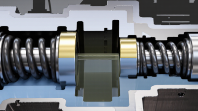
A metal bellows seal uses a flexible, welded metal element to maintain contact between two sealing faces. One face rotates with the shaft; the other remains stationary in the seal housing. The bellows provides spring force as the faces wear, while also limiting leakage along the shaft. That matters.
Unlike designs that use a sliding secondary seal on the shaft, a bellows arrangement can reduce friction at that point. Its flexibility also helps accommodate small axial movement. But it cannot correct poor alignment or rough installation. Even a robust seal can fail early if the faces run dry or become distorted.
Selection starts with the actual operating conditions: fluid composition, pressure, temperature, shaft speed, and frequent starts or stops. Check whether the bellows alloy and face materials suit the process fluid. Consider heat generated between the faces, too. A seal may tolerate high temperatures in one fluid but struggle with deposits or abrasive particles in another. Details matter.
Review the equipment’s dimensions and operating history before choosing a design. Confirm the seal’s pressure limits and installation requirements with a qualified supplier or engineer. It is tempting to treat temperature rating as the deciding figure; that can be misleading. Real service conditions rarely stay perfectly steady.
Choosing a metal bellows mechanical seal starts with the actual process, not just the equipment nameplate. Record normal and upset pressure, temperature, speed, and fluid composition. Include startup, shutdown, flushing, and possible dry-running periods. Brief spikes matter. A seal selected for steady operation may struggle during a hot restart. Identify solids, viscosity, vapor pressure, and corrosive components; these influence face materials, bellows alloy, and lubrication. The U.S. Department of Energy’s Improving Pumping System Performance sourcebook estimates that pumping systems use nearly 20% of global electricity demand. That figure is not a seal-failure statistic, but it underscores why leakage, friction, and repeat maintenance deserve attention.
Next, compare those conditions with the equipment’s limits. Check shaft size, available seal-chamber space, operating speed, shaft movement, and runout against the equipment drawings and applicable seal specifications. Metal bellows designs can suit services where elastomer compatibility or spring exposure is a concern, but bellows material still needs fluid and temperature review. Ask whether the seal sees pressure reversals, frequent cycling, or solids that could collect near the faces. A written duty profile helps suppliers assess these details. Include measured field conditions, not only design values; sensors and operators do not always tell the same story. That gap deserves a second look. Document assumptions and verify them during commissioning.
Choosing a metal bellows mechanical seal starts with the process fluid, temperature, pressure, and cycling frequency. Bellows alloys must resist corrosion and fatigue; a material that survives steady heat may still crack under repeated thermal swings. Welded and formed bellows also behave differently, so check the equipment’s actual operating cycle rather than relying on a simple material chart. Small details matter.
Seal faces need a compatible pairing. Silicon carbide offers hardness and wear resistance in abrasive service, while carbon can provide good conformability in cleaner applications. Neither choice is universal: solids, lubrication, and dry-running risk can change the outcome. Secondary seals deserve equal attention. Select elastomers or PTFE-based seals for the specific fluid and temperature, then check for swelling, hardening, or loss of elasticity. The U.S. Department of Energy’s 2006 sourcebook, Improving Pumping System Performance, estimates that pumping systems use nearly 20% of global electricity and account for 25–50% of energy use in some industrial plants. That figure describes pumping systems, not mechanical seals alone, but it underscores why leakage and reliability deserve careful review. One limitation remains: published compatibility tables cannot fully predict a real mixture’s behavior. Test the actual fluid when its composition varies.
Typical upper temperature limits for selected bellows, seal-face, and secondary-seal materials
These are representative material temperature limits, not guaranteed seal operating ratings. Actual limits depend on the specific grade, pressure, fluid, lubrication, and seal design. Check chemical compatibility and supplier specifications before selection.
How to Choose Metal Bellows Mechanical Seals
Metal bellows mechanical seals suit applications where springs may clog or process conditions demand a compact design. Compare single and dual seal arrangements against pressure, temperature, speed, and leakage-control needs. A single seal may fit a clean, stable service. A dual arrangement can add protection when fluid release or contamination matters. More components, though, can mean more installation checks.
Compatibility deserves careful review. Match the bellows alloy and seal faces to the fluid, including cleaning chemicals and occasional process upsets. Check shaft size, operating temperature, pressure changes, and startup conditions. A seal that performs well at steady temperature may struggle during frequent heat cycles. Ask for documented operating limits, then compare them with actual readings from the equipment. Specifications are useful, but field conditions can be messy. That part is easy to underestimate.
Tips: Measure the shaft and chamber before ordering. Confirm flush or barrier-fluid requirements with the equipment supplier. Record leakage, vibration, and temperature after startup; small changes can reveal a developing problem. If service history is limited, run a monitored trial before treating the selection as proven. No chart can replace that evidence.
| Evaluation dimension | Configuration or material | Typical application fit | Compatibility and operating checks | Reliability considerations | Selection guidance |
|---|---|---|---|---|---|
| Seal arrangement | Single metal bellows seal | Services where a single sealing interface and limited leakage-control complexity are appropriate. | Confirm process-fluid hazards, emissions requirements, pressure direction, temperature, and whether a separate containment system is required. | Fewer components than a dual arrangement, but leakage at the primary faces is not backed up by a second seal. | Consider for compatible, well-characterized duties when the site’s leakage and safety requirements permit a single seal. |
| Seal arrangement | Dual pressurized arrangement | Applications requiring a barrier fluid to prevent process fluid from escaping across the inboard seal. | Check barrier-fluid compatibility, supply pressure, circulation, cooling, and the effect of barrier-fluid leakage into the process. | Requires dependable barrier-fluid pressure and monitoring; loss of that support can compromise the intended containment function. | Use only with a properly engineered support system and an operating plan for pressure, temperature, and fluid-level monitoring. |
| Seal arrangement | Dual unpressurized containment arrangement | Services where leakage past the inboard seal must be collected or monitored without maintaining barrier fluid above process pressure. | Verify buffer-fluid or containment-system compatibility, vent or drain routing, and allowable leakage into the containment space. | Provides a secondary containment path, but does not make the primary seal leak-free; monitoring and safe disposal remain necessary. | Evaluate where emissions control or leak detection is important and the application permits an unpressurized secondary system. |
| Bellows pressure orientation | Internally pressurized design | Often considered where process pressure acts from the inside of the bellows assembly, subject to the seal design. | Confirm pressure direction, maximum and transient pressure, balance ratio, and the design’s pressure limits for the actual shaft size. | Pressure capability depends on bellows geometry, welds, material, and operating conditions; orientation alone does not establish a rating. | Match the seal’s specified pressure orientation to the equipment arrangement and obtain design-specific limits. |
| Bellows pressure orientation | Externally pressurized design | Often considered where pressure acts on the outside of the bellows assembly, depending on the seal construction. | Check direction of pressure loading, pressure reversals, start-up conditions, and the manufacturer’s limits for the complete assembly. | Incorrect pressure orientation or unanticipated pressure reversals can impair bellows stability and face loading. | Do not substitute for an internally pressurized design without confirming the seal’s approved operating envelope. |
| Bellows alloy | 316L stainless steel | Common starting point for many general industrial services with suitable corrosion conditions. | Assess the complete fluid composition, concentration, temperature, chlorides, contaminants, and cleaning chemicals; stainless steel is not universally corrosion-proof. | Corrosion, stress-corrosion cracking, or fatigue can shorten service life if the environment or cycling is unsuitable. | Use corrosion data for the actual service conditions and check all wetted seal parts, not only the bellows. |
| Bellows alloy | Nickel-based corrosion-resistant alloy | May be appropriate for selected aggressive chemical environments or where stainless-steel compatibility is inadequate. | Choose the specific alloy using the chemical mixture, concentration, temperature, and contaminants; different nickel alloys have different limits. | Improved resistance to a particular corrosion mechanism does not remove the need to evaluate welds, fatigue, and face materials. | Specify the alloy by service conditions and verified corrosion data rather than by a general “corrosion-resistant” description. |
| Face material pairing | Carbon-graphite against silicon carbide | A commonly used pairing for liquid services when fluid lubricity, cleanliness, and chemical compatibility are suitable. | Check abrasive solids, dry running risk, chemical attack, thermal shock, and the grade or impregnant used in the carbon face. | Carbon can wear in abrasive or poorly lubricated service; brittle silicon carbide can be damaged by impact or severe thermal shock. | Review start-up, flushing, and upset conditions as well as steady-state operation before selecting the face pair. |
| Face material pairing | Silicon carbide against silicon carbide | May suit services needing hard, wear-resistant faces, including some abrasive or corrosive duties. | Confirm the silicon-carbide grades, fluid lubricity, solids characteristics, and chemical compatibility of the actual grades. | Hard faces can offer wear resistance but remain vulnerable to chipping, misalignment, and thermal shock; dry operation can cause rapid damage. | Choose only when the liquid film, alignment, and operating procedure support reliable face lubrication. |
| Secondary sealing | Elastomer O-rings or static gaskets | Used at static joints or other locations in many seal assemblies, even when the bellows removes a dynamic shaft O-ring. | Verify chemical compatibility, temperature, swelling, decompression risk, and compatibility with cleaning or flush fluids. | A bellows design does not eliminate every elastomer; a degraded secondary seal can still cause leakage or impair operation. | Identify every wetted secondary seal and select its compound for the full operating and cleaning cycle. |
| Operating conditions | Temperature, pressure, speed, and cycling | Applies to every configuration and material selection. | Provide normal and upset values, start-up and shutdown conditions, pressure reversals, shaft speed, vibration, and thermal cycling. | Transient conditions and frequent cycling can be as important as steady-state values for bellows fatigue and face stability. | Compare the complete duty profile with the seal’s documented limits; do not infer limits from alloy names alone. |
| Equipment and installation | Pump, compressor, or rotating equipment interface | All applications, especially replacements or retrofits. | Confirm shaft or sleeve dimensions, chamber geometry, runout, misalignment, gland fit, flush plan, and applicable equipment standards. | Incorrect fit, poor alignment, excessive vibration, or inadequate lubrication can cause premature face or bellows failure. | Verify measurements and installation requirements before ordering; follow equipment and seal supplier procedures. |

Note: This table is a screening guide, not a seal rating or material approval. Actual pressure, temperature, speed, and chemical limits are design-specific and should be confirmed for the complete seal assembly under the intended operating and upset conditions.
Choose a metal bellows seal around the actual service conditions, not just the equipment name. Start with fluid chemistry, operating temperature, pressure, shaft speed, and expected thermal cycling. Check whether the bellows alloy resists corrosion in the process fluid. Also confirm the seal’s pressure and speed limits with its technical documentation. Small details matter.
Installation quality can decide whether a suitable seal performs reliably. Clean the seal faces and shaft sleeve; a single grain of grit can damage a face. Check shaft runout and alignment before fitting the seal. Follow the supplier’s setting instructions, and remove setting clips only when specified. Avoid forcing piping into position, since pipe strain can shift the pump and disturb the faces. Not just temperature.
Maintenance should track leakage, vibration, and seal-chamber temperature over time. Record normal readings, so changes become visible before a failure. The U.S. Department of Energy’s Improving Pumping System Performance sourcebook reports that pumping systems use nearly 20% of global electrical energy, and 25–50% in some industrial facilities. That is system-level data, not a seal-savings claim; it underscores the value of preventing avoidable downtime. Inspect deposits and bellows condition during planned service, especially after corrosive or high-temperature duty. Bellows fatigue can be difficult to spot early, and I would not treat a clean exterior as proof of sound metal.