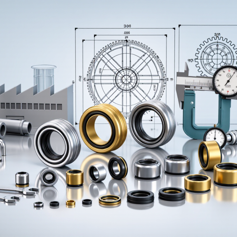
Cartridge Seal selection is a reliability decision, not merely a purchasing exercise. A well-designed cartridge unit arrives pre-assembled, helping reduce installation errors around the pump shaft. It can also simplify maintenance when process equipment operates under pressure, heat, or abrasive conditions. The details matter: face materials, elastomers, flush plans, and dimensional fit all affect service life. Small details matter.
Market data offers useful context, but it needs careful interpretation. Grand View Research valued the global mechanical seals market at approximately US$3.39 billion in 2023 and forecast growth through 2030. That figure covers mechanical seals broadly; it is not a Cartridge Seal market estimate. Heinz P. Bloch, an established machinery-reliability author, has emphasized disciplined maintenance and attention to failure causes in rotating equipment. Applied to seal purchasing, that guidance points buyers toward documented materials, application support, and clear installation instructions—not claims alone. A supplier’s test records and references deserve scrutiny. No seal is perfect.
This guide examines China’s leading Cartridge Seal manufacturers and suppliers through practical criteria: product range, engineering capability, quality controls, customization, and after-sales support. A polished catalogue can look reassuring. It cannot replace evidence. Buyers should verify specifications against actual operating conditions and ask how suppliers handle wear, leakage, and replacement parts. Some comparisons will remain imperfect because public data varies between companies. That limitation matters. The aim is a more informed shortlist, grounded in verifiable details rather than ranking language alone.
Cartridge mechanical seals arrive as preassembled units, with the seal faces and setting dimensions held in place by a sleeve and gland plate. During operation, the shaft turns the rotating face against a stationary face. A very thin film of process fluid separates them, reducing friction while limiting leakage.
It is a small gap. Too much face contact can generate heat; excessive separation can allow leakage. Springs maintain contact as pressure and movement change, while elastomer secondary seals close paths around the shaft and gland.
The main components are the rotating and stationary faces, springs, secondary seals, sleeve, gland plate, and drive collar.
The collar transfers shaft rotation to the assembly, and the gland plate locates the cartridge at the equipment chamber. That matters during installation. Technicians can avoid setting individual seal dimensions, but they still need clean faces, correct alignment, and suitable process connections.
Flush or quench arrangements vary with the service; there is no universal setup. In real operation, vibration, dry running, or incompatible elastomers can shorten service life.
The ideal operating picture is tidy. Field conditions are not always. Check equipment drawings and operating limits before selecting or fitting a cartridge seal.
Cartridge seals arrive preassembled, reducing field alignment work and the risk of handling errors. Selection still depends on fluid properties, pressure, temperature, and the consequences of leakage. A single seal is often practical for compatible, lower-risk services. For tighter containment, tandem and dual arrangements add another sealing interface. They are not interchangeable.
In a tandem arrangement, two seals operate in series, commonly with an unpressurized buffer system. API Plan 52 circulates buffer fluid through a reservoir, where level and pressure changes can help operators identify leakage. A pressurized dual arrangement uses a barrier fluid above process pressure; API Plan 53 supports this approach through different reservoir or circulation designs. The choice matters. Incorrect barrier-fluid pressure or an unsuitable fluid can undermine the intended protection.
The American Petroleum Institute’s API 682 standard provides guidance for pump sealing systems and support plans. Grand View Research estimated the global mechanical-seals market at about US$4.6 billion in 2023, reflecting broad industrial demand, not a guarantee of performance. Experienced suppliers should confirm seal faces, elastomers, operating limits, and plan instrumentation against actual process data. Small details matter. Site conditions can differ from the datasheet, and that gap deserves a careful review.
| Seal Configuration | API 682 Arrangement | Typical Support Plan | Auxiliary Fluid and Pressure | Leakage Control and Monitoring | Typical Application Considerations |
|---|---|---|---|---|---|
| Single cartridge seal | Arrangement 1: one seal between the process fluid and atmosphere | Plan 52 and Plan 53 are not single-seal plans. Common single-seal piping plans include Plan 11, Plan 13, or Plan 32, selected for the service. | No buffer or barrier-fluid system is provided by Plans 52 or 53 for this configuration. | Process-side leakage is controlled by the single seal; leakage detection and containment depend on the seal design and selected piping plan. | Often considered where the process fluid, emissions requirements, and site risk assessment permit a single seal. Check fluid properties, pressure, temperature, and applicable emissions requirements. |
| Tandem dual seal, unpressurized buffer | Arrangement 2: two seals in series with an unpressurized buffer space between them | API Plan 52 | A buffer fluid circulates in the seal support system. Its pressure is normally below seal-chamber pressure. | Leakage across the inboard seal can enter the buffer system. Buffer pressure, level, temperature, and leakage indicators can be monitored as specified for the installation. | Used where a secondary seal and collection or monitoring of inboard leakage are required, while the buffer system remains unpressurized relative to the process. |
| Dual pressurized seal | Arrangement 3: two seals with a pressurized barrier-fluid space between them | API Plan 53A, 53B, or 53C | Barrier-fluid pressure is maintained above seal-chamber pressure by the system design. The pressure differential must be set and controlled for the specific seal and service. | Barrier fluid typically leaks in small quantities toward both the process and the atmospheric side. Pressure and other system parameters are monitored to help identify loss of barrier conditions. | Considered when process-fluid leakage to atmosphere must be minimized or when the process fluid is hazardous, volatile, or difficult to handle. Barrier-fluid compatibility with the process must be assessed. |
| Dual pressurized seal with bladder accumulator | Arrangement 3 | API Plan 53A | Uses a pressurized barrier-fluid reservoir with a gas-charged bladder to maintain barrier pressure. | System pressure and fluid condition require suitable instrumentation and routine checks; reservoir capacity and heat dissipation must suit the application. | May suit services where a relatively simple pressurized barrier-fluid system is appropriate. Confirm gas charge, operating pressure, and barrier-fluid requirements with the seal-system design. |
| Dual pressurized seal with piston accumulator | Arrangement 3 | API Plan 53B | Uses a piston accumulator to separate the barrier fluid from the pressurizing gas. | Barrier pressure and accumulator condition are monitored. The system requires suitable sizing and maintenance for the expected pressure and fluid volume changes. | Can be considered where a piston accumulator is suitable for the operating conditions and the installation’s maintenance practices. |
| Dual pressurized seal with external pressure source | Arrangement 3 | API Plan 53C | Uses a reference-pressure arrangement with an external pressure source to maintain barrier-fluid pressure above seal-chamber pressure. | Pressure differential depends on the selected reference and control arrangement; instruments and safeguards should be specified for the system. | May be considered where the required pressure relationship can be reliably maintained using the available external pressure source and process-pressure reference. |

Selection note: API Plan 52 and API Plan 53 describe seal support systems, not seal configurations. Plan 52 is generally associated with an unpressurized buffer system for Arrangement 2; Plan 53 systems provide pressurized barrier fluid for Arrangement 3. Final selection, operating limits, instrumentation, and fluid compatibility should be verified against the applicable API 682 edition and the project-specific seal design.
For cartridge seal selection, record pressure at the seal chamber, not just pump discharge pressure. API 682 and ISO 21049 provide qualification frameworks, but neither makes one operating envelope suitable for every service. Temperature matters too: a hot flush or rapid startup can change face lubrication and elastomer behavior. Small details count.
Shaft speed should be checked alongside shaft diameter. A 50 mm shaft turning at 3,000 rpm has a surface speed of about 7.9 m/s, calculated from circumference and rotational speed. This is a check, not a universal limit. The U.S. Department of Energy’s 2014 pump-system sourcebook estimates that pumping systems use nearly 20% of global electricity, underscoring the value of avoiding unnecessary friction and repeated seal failures.
Specify leakage measurement conditions, units, and timing. A brief startup trace and steady-state leakage are not the same observation. Record fluid, pressure, temperature, speed, and leakage together; otherwise, comparisons between suppliers can mislead. I would also flag uncertainty: field readings can be inconsistent, especially when collection methods differ. API 682’s test framework helps establish repeatable checks, while the final acceptance limit should match the process risk and documented service conditions.
For cartridge seal manufacturers and suppliers, API 682 Fourth Edition and ISO 21049 offer useful benchmarks for evaluating design and documentation. They address shaft sealing systems for centrifugal and rotary pumps in demanding process services. The standards help buyers specify seal arrangements, support systems, materials, and installation details. Edition matters: API 682 Fourth Edition includes requirements that may not appear identically in older ISO 21049 references. Confirm the applicable clauses before comparing quotations.
A practical review starts with the pump’s operating conditions. Record pressure, temperature, speed, fluid composition, and expected start-stop cycles. Then check whether the proposed cartridge design and seal support plan suit those conditions. Ask for clear dimensional drawings, material specifications, and relevant test records. Check the documents. A polished data sheet alone does not demonstrate that a complete assembly meets a project specification.
Suppliers should explain deviations instead of hiding them in broad claims of compliance. Buyers can compare scope, documentation, and service support using the same project requirements. Site experience also matters: installation access, sleeve condition, and piping layout can affect reliability. Standards cannot predict every field issue. Even careful reviews leave room for judgment, and that is worth acknowledging.
A cartridge seal supplier should match face materials, elastomers, and metal parts to the actual fluid and operating conditions. Silicon carbide faces can suit abrasive service; carbon faces often work in cleaner fluids. Neither is universal. Ask suppliers to confirm chemical compatibility, temperature limits, pressure range, and shaft dimensions in writing. A material table alone is not enough.
Testing matters as much as material selection. API Standard 682 sets technical requirements for mechanical seals in petroleum, petrochemical, and natural-gas service. Request documented pressure-test procedures, inspection records, and traceability for wetted parts. The U.S. Department of Energy’s 2006 Improving Pumping System Performance sourcebook notes that pumping systems can consume 25–50% of energy in some industrial facilities. A seal does not determine that figure, but leakage and unplanned shutdowns can add avoidable operating costs. Check how a supplier handles test failures, too. This is often overlooked.
Tips: Send the supplier fluid composition, temperature, pressure, and site photos before requesting a quote. Ask whether tests are type qualification or routine checks on each unit. Small detail, big difference. Be cautious when a quote promises a universal solution; real service conditions are rarely that tidy.
Hardness is one factor when selecting cartridge seal face materials; chemical compatibility, temperature, pressure, lubrication, and operating conditions also matter. Values shown are representative midpoints of approximate ranges: carbon graphite 1–2, alumina 9, silicon carbide 9–9.5, and tungsten carbide 8.5–9. Actual properties vary by grade and composition.